- 您现在的位置:买卖IC网 > Sheet目录3753 > ATMEGA169P-16MCHR (Atmel)MCU AVR 16KB FLASH 16MHZ 64-VQFN
PIC16F946
DS41265A-page 168
Preliminary
2005 Microchip Technology Inc.
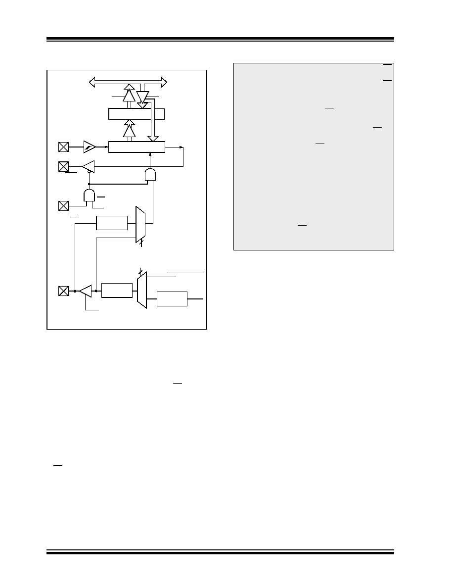
FIGURE 14-1:
SSP BLOCK DIAGRAM
(SPI MODE)
To enable the serial port, SSPEN bit (SSPCON<5>)
must be set. To reset or reconfigure SPI mode:
Clear bit SSPEN
Re-initialize the SSPCON register
Set SSPEN bit
This configures the SDI, SDO, SCK and SS pins as
serial port pins. For the pins to behave in a serial port
function, they must have their data direction bits (in the
TRISC register) appropriately programmed. This is:
SDI must have TRISC<7> set
SDO must have TRISC<4> cleared
SCK (Master mode) must have TRISC<6>
cleared
SCK (Slave mode) must have TRISC<6> set
SS must have TRISA<5> set.
.
Read
Write
Internal
Data Bus
RC7/RX/
RC4/T1G/
RA5/AN2/
RC6/TX/CK/
SSPSR reg
SSPBUF reg
SSPM<3:0>
bit 0
Shift
Clock
SS Control
Enable
Edge
Select
Clock Select
TMR2 Output
TCY
Prescaler
4, 16, 64
TRISC<6>
2
Edge
Select
2
4
SCL/
Peripheral OE
SDA/SEG8
DT/SDI/
SDO/SEG11
C2OUT/SS/
SEG5
SCK/
SEG9
Note 1: When the SPI is in Slave mode with SS
pin control enabled (SSPCON<3:0> =
0100
), the SPI module will reset if the SS
pin is set to VDD.
2: If the SPI is used in Slave mode with
CKE = 1, then the SS pin control must be
enabled.
3: When the SPI is in Slave mode with SS pin
control enabled (SSPCON<3:0> = 0100),
the state of the SS pin can affect the state
read back from the TRISC<4> bit. The
peripheral OE signal from the SSP module
into PORTC controls the state that is read
back
from
the
TRISC<4>
bit
(see
(Extended)” for information on PORTC).
If read-modify-write instructions, such as
BSF,
are performed on the TRISC register
while the SS pin is high, this will cause the
TRISC<4> bit to be set, thus disabling the
SDO output.
发布紧急采购,3分钟左右您将得到回复。
相关PDF资料
2-1546217-0
TERM BLK RCPT 20POS SIDE 5.08MM
1-1546217-9
TERM BLK RCPT 19POS SIDE 5.08MM
1-1546217-8
TERM BLK RCPT 18POS SIDE 5.08MM
1-1546217-7
TERM BLK RCPT 17POS SIDE 5.08MM
1-1546217-6
TERM BLK RCPT 16POS SIDE 5.08MM
1-1546217-5
TERM BLK RCPT 15POS SIDE 5.08MM
1-1546217-4
TERM BLK RCPT 14POS SIDE 5.08MM
1-1546217-3
TERM BLK RCPT 13POS SIDE 5.08MM
相关代理商/技术参数
ATMEGA169P-16MCU
功能描述:8位微控制器 -MCU AVR 16KB, 512B EE 16MHz 1KB SRAM, 5V
RoHS:否 制造商:Silicon Labs 核心:8051 处理器系列:C8051F39x 数据总线宽度:8 bit 最大时钟频率:50 MHz 程序存储器大小:16 KB 数据 RAM 大小:1 KB 片上 ADC:Yes 工作电源电压:1.8 V to 3.6 V 工作温度范围:- 40 C to + 105 C 封装 / 箱体:QFN-20 安装风格:SMD/SMT
ATMEGA169P-16MU
功能描述:8位微控制器 -MCU AVR 16K FLASH 512B EE 1K SRAM LCD ADC RoHS:否 制造商:Silicon Labs 核心:8051 处理器系列:C8051F39x 数据总线宽度:8 bit 最大时钟频率:50 MHz 程序存储器大小:16 KB 数据 RAM 大小:1 KB 片上 ADC:Yes 工作电源电压:1.8 V to 3.6 V 工作温度范围:- 40 C to + 105 C 封装 / 箱体:QFN-20 安装风格:SMD/SMT
ATMEGA169P-16MU SL383
制造商:Atmel Corporation 功能描述:MCU 8BIT ATMEGA RISC 16KB FLASH 3.3V/5V 64PIN MLF - Tape and Reel
ATMEGA169P-16MUR
功能描述:8位微控制器 -MCU AVR LCD 16KB FLSH EE 512B 1KB SRAM-16MHZ RoHS:否 制造商:Silicon Labs 核心:8051 处理器系列:C8051F39x 数据总线宽度:8 bit 最大时钟频率:50 MHz 程序存储器大小:16 KB 数据 RAM 大小:1 KB 片上 ADC:Yes 工作电源电压:1.8 V to 3.6 V 工作温度范围:- 40 C to + 105 C 封装 / 箱体:QFN-20 安装风格:SMD/SMT
ATMEGA169P-8AU
制造商:ATMEL 制造商全称:ATMEL Corporation 功能描述:Microcontroller with 16K Bytes In-System Programmable Flash
ATMEGA169P-8MU
制造商:ATMEL 制造商全称:ATMEL Corporation 功能描述:Microcontroller with 16K Bytes In-System Programmable Flash
ATMEGA169PA
制造商:ATMEL 制造商全称:ATMEL Corporation 功能描述:8-bit Microcontroller with 16K Bytes In-System Programmable Flash
ATMEGA169PA_1
制造商:ATMEL 制造商全称:ATMEL Corporation 功能描述:High Endurance Non-volatile Memory segments